Figure1 Setting terminal position
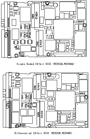
Setting Terminals The user must set the following terminals and SCSI terminating resistor before installing the HDD in the system.Fujitsu M2932xx/M2934xx:Switch Settings
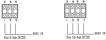
Setting terminal:CN4, CN6, CN7, CN10Figure 1 shows the setting terminal and the position of the SCSI terminating resistor modules.
Figure1 Setting terminal position
Figure 2 Setting terminals(CN4)
Table 1 8-bit SCSI SCSI ID setting(CN4)
| SCSI ID | 5-6 | 3-4 | 1-2 |
|---|---|---|---|
| 0 | OPEN | OPEN | OPEN |
| 1 | OPEN | OPEN | SHORT |
| 2 | OPEN | SHORT | OPEN |
| 3 | OPEN | SHORT | SHORT |
| 4 | SHORT | OPEN | OPEN |
| 5 | SHORT | OPEN | SHORT |
| 6 | SHORT | SHORT | OPEN |
| 7* | SHORT | SHORT | SHORT |
Table 2 16-bit SCSI SCSI ID setting(CN4)
| SCSI ID | 7-8 | 5-6 | 3-4 | 1-2 | SCSI ID | 7-8 | 5-6 | 3-4 | 1-2 |
|---|---|---|---|---|---|---|---|---|---|
| 0 | OPEN | OPEN | OPEN | OPEN | 8 | SHORT | OPEN | OPEN | OPEN |
| 1 | OPEN | OPEN | OPEN | SHORT | 9 | SHORT | OPEN | OPEN | SHORT |
| 2 | OPEN | OPEN | SHORT | OPEN | 10 | SHORT | OPEN | SHORT | OPEN |
| 3 | OPEN | OPEN | SHORT | SHORT | 11 | SHORT | OPEN | SHORT | SHORT |
| 4 | OPEN | SHORT | OPEN | OPEN | 12 | SHORT | SHORT | OPEN | OPEN |
| 5 | OPEN | SHORT | OPEN | SHORT | 13 | SHORT | SHORT | OPEN | SHORT |
| 6 | OPEN | SHORT | SHORT | OPEN | 14 | SHORT | SHORT | SHORT | OPEN |
| 7 | OPEN | SHORT | SHORT | SHORT | 15* | SHORT | SHORT | SHORT | SHORT |
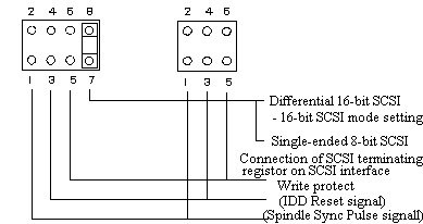
note)SCA Connector Specification is not supported on this function.
     1,2 pins are not connected.
Figure 3  Setting terminals(CN6)
Table 3 Motor start mode setting(CN6 1-2)
| Start timing of the spindle motor | 1-2 |
| Starting of the motor is controlled with the START/STOP UNIT command | OPEN |
| The motor is started immediately after the power supply is turned on or the microcode is downloaded | SHORT* |
(2)SCSI bus parity
Table 4 SCSI bus parity setting(CN6 3-4)
| SCSI data bus parity check by HDD | 3-4 |
| Not performed | OPEN |
| Performed | SHORT* |
(3)Offline self-diagnostics
Table 5 Offline self-diagnostics setting(CN6 5-6)
| Offline self-diagnostics | 5-6 |
| Stopped(normal operation mode) | OPEN* |
| Executed(diagnostics mode) | SHORT |
+ Single-Ended type, 8-bit SCSI  + Differential type,  8-bit SCSI
+ Single-Ended type,16-bit SCSI  + Differential type, 16-bit SCSI

Figure 4 Setting terminals(CN7)
Table 6 Write protect setting(CN7 5-6)
| Write protect | 5-6 |
| Write operation is enabled | OPEN* |
| Write operation is disabled | SHORT |
Table 7 Setting the connection of terminating resistor on SCSI interface(CN7 7-8)
| Connection of the terminating resistor on the SCSI interface | 7-8 |
| Terminating resistor circuit is not connected | OPEN |
| Terminating resistor circuit is connected | SHORT* |
(3)16-bit SCSI mode setting(Differential type, 16-bit SCSI)
Set setting terminal CN7 7-8 to enable or disable the 16-bit SCSI mode(See Table 8). When the 16-bit SCSI mode is enabled, all data bus (DB00 to DB15, DBP0 toDBP1) can be effective.
When the Differential type 16-bit SCSI HDD is used as 8-bit SCSI device, this setting must be open.
Table 8 16-bit SCSI mode setting(CN7 7-8)
| SCSI mode | 7-8 |
| 8-bit SCSI mode setting | OPEN |
| 16-bit SCSI mode setting | SHORT* |
Figure 6 Setting terminals(CN10)(for single-ended type 16-bit SCSI)
| Connection of the terminating resistor on the SCSI interface | 3-4 | 1-2 |
| Terminating resistor circuit is not connected | OPEN | OPEN |
| Terminating resistor circuit is connected | SHORT* | SHORT* |
Table 10 shows the setting of connection of the terminating resistor when the 16-bit SCSI model is used as 8-bit SCSI model.
Table 10 Setting connection of terminating resistor on SCSI interface
| Connection of the terminating resistor on the SCSI interface | 3-4 | 1-2 |
| Terminating resistor circuit is not connected | OPEN | OPEN |
| Terminating resistor circuit is connected | SHORT* | SHORT* |
to the table of contents!!